
3D Viewport
The 3D viewport is not a separate page — it is the body of every viewer that
shows geometry, meshes, or fields. Learn the controls once and they work in the
CAD viewer, the mesh viewers, the results viewers, and the editors that embed one
— Ferro, .nvm, .nvs, .nvpost, and .stella.
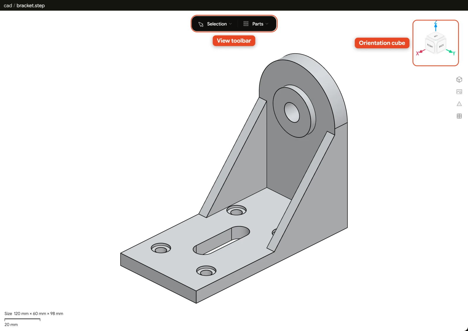
Mouse navigation
| Input | Action |
|---|---|
| Right-drag | Orbit |
| ⌃ + left-drag | Orbit — same as right-drag, for trackpads |
| Middle-drag | Pan |
| ⇧ + right-drag | Pan — laptop fallback for the middle button |
| Scroll | Zoom |
| Left-click | Select the entity under the cursor |
| ⇧ + left-click | Extend the selection |
Orbiting picks up its pivot from what is under the cursor when you start the drag, so you rotate around the feature you are looking at rather than around some distant scene centre. Whichever button you orbit with, the pivot is chosen the same way — the button you use does not change what you orbit around. In the CAD viewer, a drag that starts on empty space beside the geometry turns around the centre of the bodies that are not hidden, so the model turns in place instead of swinging out of view.
Panning is CAD-style: the point under the cursor stays under the cursor.
Zoom is exponential — roughly 3% per scroll notch — and scaled to the size of the scene, so a 2 mm fastener and a 40 m hull both zoom at a usable rate.
The orientation cube
The widget in the corner is a view cube. Click a face for that orthographic view, an edge to split the difference, or one of the eight corner buttons for the corresponding isometric. Three axis arrows mark X, Y, and Z.
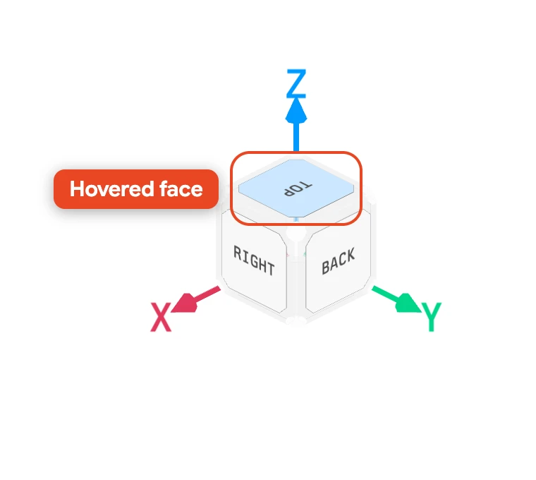
The back faces are larger than the front faces on purpose — they are forgiving click targets, so a near-miss still does what you meant.
Size and scale
A scale bar in the bottom-left corner of a CAD viewport marks a round distance
at the current zoom, with a Size line above it: the model's bounding-box
extents along X, Y, and Z, each in the metric unit nearest its magnitude —
120 µm, 30 mm, 2.5 m.
A .msh tab, or a surface or model tab (.stl, .obj, .glb, .gltf), gets
neither. A .msh, an STL and an OBJ carry no length unit, so printing their
coordinates as metres would assert something the file never said.
Qubis works in metres, so a file that declares one length unit and stores another arrives a thousand times too small or too large. The size read-out is where that shows up: a bracket you expect in millimetres reading as micrometres is a mis-declared file, not a camera problem.
Agent-controlled views
The agent can use prism_set_camera to choose a named view — including the six
axis views and isometric corners — or to set an explicit camera position,
target, and up vector. The explicit form is useful when you need to reproduce
the same framing across two results. The move is immediate, so the view is
settled when the tool returns.
An NVPOST view remembers its camera — however you moved it, by hand or through
prism_set_camera — and restores it when you switch threads or reopen the
document. It is saved to [view.camera] in nvpost_config.toml, so it travels
with the document. A view you have never moved frames itself automatically.
prism_export_view saves a 3D viewer as a PNG. It can use the scene, a
transparent background, or white, and can include the legend and a scale. The
agent should open the returned file and inspect it before using the image in a
report.
Both target the viewer you are looking at unless the agent names a file, and
both bring that tab on screen — so pointing the camera and then exporting
captures the view just set. The agent can point any viewer that has a camera;
export is narrower, reading the CAD (.step / .stp), Ferro, and .nvpost
viewers, and only once the tab has loaded its geometry. Both need the file open
in a tab, and with a full-width page in front — Settings, Solver Desk, Plugins,
Scheduled —
they fail at once rather than waiting for a frame.
Backgrounds
The Background button opens a picker listing every mode with a swatch of what it looks like, and a check on the one in use:
| Mode | Look |
|---|---|
| White | Flat white — the default |
| Light Gray | Near-white fading to a soft grey |
| Light Gradient | Near-white fading to light steel-blue |
| Mid Gray | Neutral mid-grey studio gradient |
| Studio Dark | Navy structural gradient |
| Black | Flat black, for high-contrast capture |
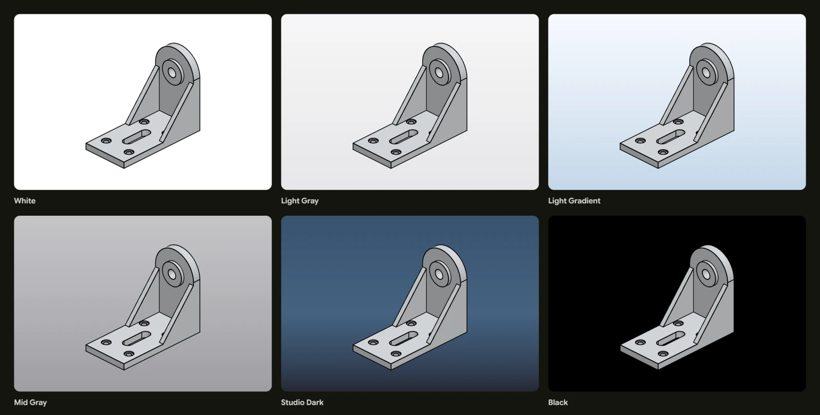
The picker closes on Esc, on a click in the viewport, and on any of the display buttons beside it.
The same modes are in Settings → General → 3D viewport → Default viewport background, which is the same setting rather than a separate default: picking one there changes every viewport too. Use Black or Studio Dark for a figure that wants contrast, and a light mode for one going onto a page.
Selection
Left-click selects the entity under the cursor via a raycast against the actual geometry, so what you click is what you get — not the nearest bounding box.
⇧-click adds to the selection.
What a selection means depends on the viewer: a face to constrain in a structural case, a patch to assign a boundary condition to, a triangle to inspect.
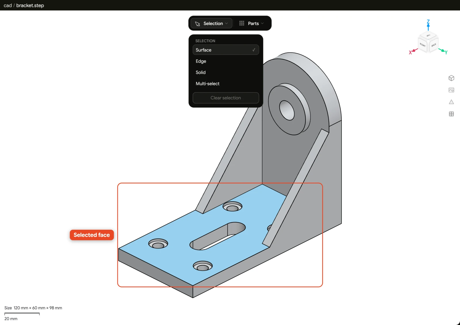
In the CAD viewer, what a click takes is a mode you set — see below.
The CAD viewer
A STEP tab has no ribbon and no outline pane. Everything the viewer can be asked
for hangs off a floating rail, whose Selection and Parts entries each
open a card. CAD, .msh, and surface and model tabs (.stl, .obj, .glb,
.gltf) all open ORTHOGRAPHIC rather than perspective, so parallel lines
stay parallel and a solid's silhouette reads true; the projection button below
the orientation cube switches the focused pane.
Selection modes
The Selection card decides what a click takes:
| Mode | What a click selects |
|---|---|
| Surface | The face under the cursor — the default |
| Edge | The B-rep edge nearest the cursor |
| Solid | The whole body the face under it belongs to |
Hovering pre-highlights what a click would take, so you can see the face, edge, or body before committing to it. Multi-select below the modes is a toggle rather than a held key: leave it on and every click adds. Clear selection is lit only when something is selected, which also makes it the answer to "is anything selected?".
The mode survives a reload; the selection does not.
While a large model is still streaming in, the parts you can see as placeholder outlines are not yet selectable — they become pickable as their geometry arrives.
Parts
The Parts card lists the assembly's bodies with their face counts. Selecting a row selects that body's faces. Each row has a visibility toggle, and a body you hide there stops taking clicks — it no longer blocks what it was covering, and its faces and edges leave the selection with it. Show all in the card's header brings hidden bodies back, and appears only while something is hidden. Tint: on / off beside it colours the bodies apart instead of shading them all as one material.
Seams
A CAD tab draws B-rep seams — the boundaries between the surfaces a solid is built from. SEAMS: ON / OFF, in the column of display buttons under the orientation cube, hides them. Edges you have selected stay drawn and clickable either way.
The mesh viewers
A .msh tab, a surface tab (.stl, .obj) and a model tab (.glb, .gltf)
use the same chrome as the CAD viewer: a full-width viewport with a floating
rail over it, and no ribbon. The rail's entries differ by what the format
carries.
| Tab | Rail entries |
|---|---|
.msh | Info, Quality, Sets |
| Surface | Info, Quality, View |
| Model | Info, View |
Info counts what loaded. A .msh gives Nodes and Elements, with a
breakdown under ELEMENT TYPES. A surface gives Points and Faces,
plus a TOPOLOGY section. A model tab is the same chrome over a scene you are
only looking at: its card reads MODEL and counts Triangles alone,
because its points are its primitives' own, repeated wherever they meet. A
model carries neither the topology check nor the quality metrics, so Quality
is not on its rail.
TOPOLOGY starts with a Check button rather than an answer: closing the surface up is a half-edge build, and a large surface need not pay for it just to be looked at. Press it and the row reads Checking…, then Watertight, Surface with boundary, or Non-manifold, in green, amber or red, with Leftover triangles and Boundary loops beneath it when there are any. A check that fails leaves Check where it was, with the error under it.
LOAD NOTES appears at the foot of the card when the file needed repairing to
load — a malformed STL header, say — and says what was done. An .obj never
produces one.
Quality paints the mesh by one metric instead of its material colour. None turns it off; the metrics themselves differ, because the two formats are measuring different things:
| Tab | Metrics |
|---|---|
.msh | Aspect Ratio, Skewness, Jacobian, over the volume elements |
| Surface | Aspect Ratio, Skewness, Min Angle, over the faces |
The colour bar appears with the metric, and double-clicking the bar opens the colour-scale editor as it does anywhere else.
Sets lists the named node and surface sets a .msh declares, each with its
count; clicking one selects it, and Clear appears in the card's header while
something is selected. View holds a surface or model tab's SHADING
choice, Flat or Smooth.
Clicking an element in a .msh opens an ELEMENT n card giving its Type,
Aspect ratio, and area or volume.
The VTU viewer
A VTK-family tab — .vtu, .vtk, .pvtu, .pvd, and CalculiX's .frd —
opens in the VTU viewer, which takes the same chrome as an .nvpost view: a
full-width viewport, a floating rail, and no ribbon. The rail reads Info,
Step, Field, in that order, and offers only what the file supports.
| Entry | What it holds | When it appears |
|---|---|---|
| Info | The file name, with Points and Cells, and Steps when there is more than one | Always |
| Step | Every step in the file; click one to show it | Past one step |
| Field | What paints the surface, under SCALARS, VECTORS and COORDINATES, with none for bare geometry | Once the file has loaded |
Scale…, in the FIELD card's header while a field is painted, opens the colour-scale editor — a Colormap row, a histogram of the values, the Data extent the field actually spans, Min and Max to clamp it to, and Reset once you have overridden the range. Double-clicking the colour bar opens the same editor, as it does in any other viewer. Edges are not on the rail: EDGES: ON / OFF, in the column of display buttons under the orientation cube, draws them, as does Toggle Edges in the viewport's right-click menu.
A file with more than one step also gets a step bar under the viewport. A run
over time — a .pvd series, a .frd's increments — gets a scrubber and a play
control: Prepare to play loads every step first, and once it has, a button
at the end of the bar cycles the rate through 6, 12, 24, 48 and 60 fps. A
preparation that does not finish leaves Retry prepare. A file of separate
states instead — modes, independent load cases — gets a point per step to
click, and no play control, because playing through them would mean nothing.
Nothing in the tab is saved: the field and step you pick last as long as the
tab does. The viewer paints the source's own surfaces, undeformed, and has
neither cutting filters nor a deformation scale — an .nvpost view is where a
slice, clip, threshold, isosurface or warp lives, and it will take a .vtu, a
.pvd, or an .stl or .obj surface as its source.
In an .nvpost view, what paints a surface lives in Scene rather than in a
Field entry of its own. Scene opens a card over the viewport: every
source with its PATCHES and FILTERS on the left, narrowed by the search
band above them, and the settings of whichever you select on the right. Add
source draws another case or dataset into the same view; Add filter cuts
the source it sits under. A source carries Visible or Hidden, with
Hide / Show to change it, and a hidden source is not read while the
card is closed and it is not the selected one. Its DATA settings —
Location, a Model deck for a results file that needs one, and
Subcase — are its own, not the view's.
Esc closes the card.
Color by sits under APPEARANCE, for the view and for each surface in it. A field the file stores per cell adds Cell values beside it — Per cell paints each cell flat, Averaged spreads the value over the points it touches. A surface that has not been given a field of its own leads with a Source field (…) chip in Color by and a Source (…) chip in Cell values, each naming what the view is using.
Each drawn source with more than one step gets its own step bar under the viewport, stacked, and once two sources are drawn every bar opens with the source's name so you can tell them apart.
3D mice
Qubis supports 3Dconnexion SpaceMouse devices through the 3DxWare driver, so the driver computes camera motion exactly as it does in your other CAD applications.
Install the 3DxWare driver, plug in the device, and it drives whichever viewport has focus. If you would rather it did not, turn it off in Settings → General → 3D viewport.
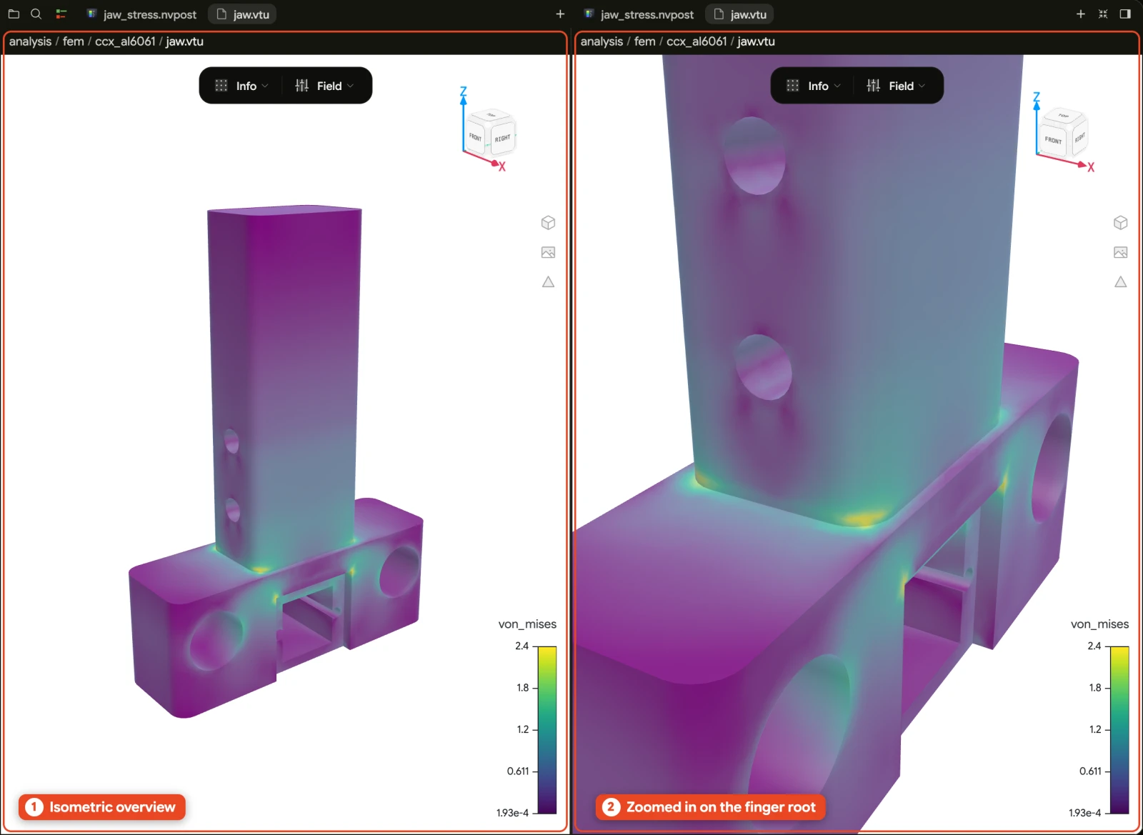
Working with panes
The viewport is a pane like any other, which is what makes side-by-side work possible:
- Split with ⌘\ and put the case file beside the geometry it configures.
- ⌘1–⌘9 focus a pane by index.
- Each pane keeps its own camera, so one can hold an isometric overview while another sits zoomed into a fillet.
Performance
Large models are handled with a bounding-volume hierarchy built on demand for picking, and level-of-detail rendering for display. The first interaction with a very large mesh can pause briefly while that structure is built; after that picking is fast.
If the viewport is slow on a model you consider small, check that you are not looking at a mesh with far more elements than you think — the mesh viewers report element counts.